


A feed mill machine can be mechanically suitable for a production target and still fail to deliver dependable commercial output if the project is not prepared around it. The gap is often outside the machine itself: incomplete foundations, an insufficient electrical supply, unavailable steam, poorly planned conveying interfaces, or commissioning that ends before operators can repeat the required conditions. Installation readiness should therefore be treated as an engineering workstream, not a delivery-day activity.
The buyer, civil contractor, electrical team, equipment supplier and production manager need agreed responsibilities, documented interfaces and measurable acceptance conditions before the line is started. This guide explains how to prepare a feed mill installation, interpret equipment data without confusing machine capacity with whole-plant output, and organize commissioning for repeatable production.
1. Define the Production Duty Before Finalizing Equipment
“Animal feed” is not a sufficiently precise design basis. Poultry, pig, cattle and other feed products can differ in formulation, particle size, pellet diameter, conditioning requirements and production sequence. Those differences affect the equipment configuration and utilities required at start-up. A line designed around one product may not automatically deliver the same output or product quality when the formulation or pellet specification changes.
Before finalizing the layout, document feed types and formulations, raw materials and their normal moisture variation, finished-feed form and pellet sizes, product changeover frequency, target saleable output per hour, planned operating hours, and the process stages included in the project. Confirm whether the scope includes receiving, cleaning, grinding, batching, mixing, conditioning, pelleting, cooling, screening, conveying and packing, or only selected stages. Record seasonal or supplier-related changes in raw-material properties if they are expected to affect normal operation.
These details establish the duty against which the plant should be designed and tested. A machine’s published capacity is a reference for a particular model and operating context. It is not automatically the guaranteed output of the complete feed mill. Grinding and mixing, formulation, conditioning, operator settings, cooling and screening can all constrain saleable throughput. The buyer should therefore distinguish the capacity of an individual machine from the output of the integrated process.
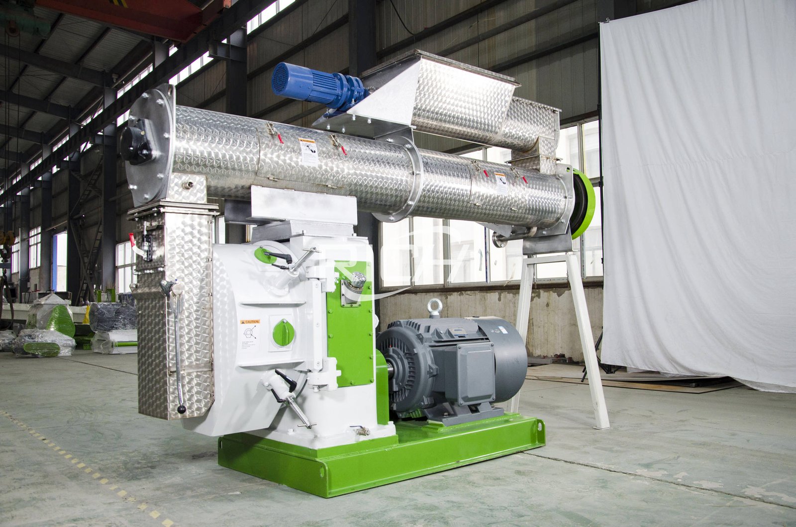
The RICHI product page for the SZLH-420 feed mill machine lists a nominal capacity range of 8–12 t/h and a 110 kW main motor. Those figures identify the published model configuration; they do not remove the need to confirm the customer’s feed formula, pellet specification, operating conditions and complete-line balance. Buyers should review the exact SZLH-420 feed mill machine specifications alongside their own production duty.
2. Translate the Process Flow Into Physical Interfaces
A process flow diagram must be translated into physical interfaces. Each machine needs an identified incoming and outgoing material route, maintenance access, a safe working area and a clear connection to utilities. The installation drawing should show these interfaces before foundations or steel platforms are finalized. The process engineer should identify which equipment must operate together and which sections need intermediate bins or buffer capacity.
Use an interface register for every equipment item. Record its tag, location, foundation or support requirement, inlet and outlet connection, electrical load, control signal, dust extraction point, access requirement and responsible contractor. Add the drawing number and revision used for coordination. This makes omissions visible while the project can still correct them on drawings, rather than after equipment has arrived.
Pay particular attention to transfer points. A pellet mill may be correctly installed, but a poorly aligned conveyor, undersized chute or inconvenient buffer arrangement can interrupt feeding and create material accumulation. Check the complete route, including access for clearing blockages and replacing wear parts. The layout should also show safe operator movement, forklift routes where needed, and how maintenance components will be lifted or removed.
3. Prepare the Building, Foundations and Maintenance Space
The civil contractor should work from the latest approved general arrangement and equipment foundation drawings, not preliminary sketches or assumed dimensions. Confirm floor elevations, anchor-bolt positions, embedded plates, openings, pits and steel-platform interfaces before concrete work is closed out. A drawing revision register helps prevent construction teams from using superseded information.
Foundation design must follow the supplier’s drawings and the project’s structural engineering requirements. Do not assume that a heavier concrete block is automatically a better foundation. The required support depends on the machine, operating loads, vibration characteristics, anchoring arrangement and building structure. Any change to the foundation or machine position should be reviewed before installation, with the revised dimensions recorded for the installation team.
Maintenance access is a frequent source of late changes. Check that technicians can open guards and doors, remove motors or rollers, handle dies and screens, reach lubrication points and withdraw components without dismantling unrelated equipment. Allow space for lifting equipment and safe movement of replacement parts. A layout that fits on paper but prevents routine maintenance can increase downtime after handover.
Before equipment arrives, verify that floors are cured and clean, delivery and lifting routes are available, unloading space is ready, and temporary storage protects electrical components and precision parts from moisture and impact. Confirm that lifting equipment has suitable capacity and access. Record site deviations and obtain approval for their resolution instead of improvising changes during unloading.
4. Verify Electrical and Utility Capacity
The main motor rating is only one part of the electrical design. The complete load schedule should include feeder motors, conditioners, conveyors, elevators, grinders, mixers, fans, dust collectors, cooling equipment, packing equipment and auxiliaries included in the project. The electrical engineer should check starting method, simultaneous operating loads, protection, cable sizing, voltage drop, earthing and control-circuit requirements. The operating sequence matters because not every motor necessarily starts or runs at the same time.
Do not size the plant supply by adding only the main motor ratings or by assuming every motor runs at full load continuously. Use the approved equipment list and operating sequence. Define who supplies the transformer, distribution panels, cables, cable trays, local isolators and field wiring. The boundary between supplier scope and buyer scope should be explicit in the technical offer and installation documents.
Steam and compressed air need the same discipline. Where steam conditioning is specified, confirm boiler capacity, fuel availability, steam pressure and quality at the point of use, condensate management, pipe routing, insulation, traps and safety provisions. The conditioner cannot be evaluated independently of the steam system. If compressed air is required, verify pressure, flow, air treatment and receiver capacity under the expected simultaneous demand.
Dust collection should be coordinated with process equipment and the building arrangement. Identify extraction points, duct routes, cleaning access, filter maintenance and safe dust handling. The design must reflect the actual material and local safety requirements; a generic fan rating is not proof that every transfer point will be adequately controlled. Utility checks should be documented before the commissioning team schedules a material trial.
5. Coordinate Delivery and Mechanical Installation
Before dispatch, agree on the equipment list, packing list, installation drawings, lifting points, foundation interfaces and delivery sequence. Identify who receives and checks equipment, who reports transport damage and where each package will be stored. Missing or damaged components should be documented before installation progresses. Keep small parts, fasteners, sensors and manuals associated with their equipment tags so they are available when needed.
During mechanical installation, check equipment identity against the approved layout, orientation, elevation, anchoring, alignment and connections to adjacent machines. Conveyors and elevators should be inspected for alignment and free movement. Guards and access covers should be fitted before operation. Lubrication points, belt tension, coupling alignment and fastener checks should follow the relevant equipment manuals. Any field modification should be recorded and reviewed for its effect on safety and process performance.
Electrical work should be inspected separately from mechanical completion. Verify motor nameplates, cable identification, terminal connections, earthing, overload settings, emergency stops, interlocks and direction of rotation. Control logic should be checked against the agreed sequence, including permissives that prevent upstream equipment from feeding a stopped downstream machine. Confirm that the operator can identify local and central controls and knows how to isolate equipment safely.
Use a pre-start checklist and record each result. A machine should not be energized simply because installation looks complete. Open defects need an owner, due date and closure record. Guards, emergency stops and protective devices are release conditions, not optional items to be corrected after production begins. The project manager should confirm that the mechanical, electrical and utility teams have all signed their respective completion checks.
6. Commission the Line in Controlled Stages
Commissioning should progress from individual equipment checks to integrated production. A practical sequence begins with static inspection of installation, fasteners, guards, lubrication, electrical connections, instruments and utility connections. The next stage is a no-load test, where permitted by the equipment procedure, to check rotation, abnormal noise, vibration, temperature, leakage and control response.
After individual checks, test emergency stops, alarms, upstream and downstream permissives, and safe shutdown behavior. Introduce the agreed raw material in a controlled sequence and check feeding, transfer, accumulation, dust extraction and process stability. Only then proceed to a product trial using the agreed formulation and pellet specification. Record machine settings, output, product quality and operating observations for each trial.
For a pellet mill, the trial record should identify the feed formula, raw-material condition, grinding result, conditioner settings, steam conditions where applicable, die specification, feeder setting and finished pellet requirements. If output or pellet quality is below target, investigate the complete process rather than changing one machine setting without understanding the cause. A restriction in grinding, mixing, steam supply or cooling may appear as a pellet-mill problem even when the press itself is operating normally.
Do not report a successful commissioning result from an isolated peak-output reading. Define the measurement period, material and formulation, product specification, sampling method, operating configuration and treatment of start-up or changeover time. Distinguish gross machine throughput from saleable product after cooling, screening and any rework. A repeatability run under the same documented conditions is more useful than a brief peak that cannot be reproduced.
7. Train Operators to Repeat the Tested Conditions
Operator training should cover more than start and stop buttons. Production staff need to understand process sequence, material-flow limits, normal operating indicators, product changeovers, lubrication routines, wear-part inspection, cleaning, safe isolation and responses to common alarms. Training should explain which adjustments are permitted during normal operation and which require maintenance or supplier support.
Training should be hands-on and linked to the actual plant. Operators should demonstrate how to check incoming material, verify the selected formula, confirm the correct die and product setting, monitor conditioner operation, inspect pellets after cooling and identify abnormal noise, vibration or temperature. Maintenance staff should understand the inspection schedule and how to document part replacement. Attendance alone is not proof of competence; use practical demonstrations for critical tasks.
Prepare operating records that capture shift, product, formulation, raw-material batch, machine settings, output, downtime, quality checks and corrective actions. These records help distinguish a machine problem from a raw-material, utility, process or operator issue. They also provide a baseline for future process optimization without relying on memory or informal shift handovers.
8. Agree on Acceptance Criteria Before the Trial
Acceptance should be agreed before commissioning, not negotiated after installation. The contract and technical annex should identify equipment and scope covered, buyer responsibilities, test material, target product, test duration, measurement method, utility conditions and evidence required for sign-off. If the buyer expects a particular output, the conditions under which that output is measured must be clear to both parties.
Separate mechanical completion from functional performance, product conformity, production performance and handover readiness. Mechanical completion asks whether equipment is installed according to approved drawings, with guards and access provisions complete. Functional performance checks motors, controls, interlocks, alarms and process equipment. Product conformity checks the agreed pellet size and quality criteria. Production performance checks saleable throughput under documented test conditions. Handover readiness confirms that manuals, drawings, training records, maintenance instructions and open-item records have been delivered.
Each criterion needs an objective verification method and a named party responsible for witnessing or approving it. If a test fails, record operating conditions, evidence, corrective action and retest result. This creates a traceable handover rather than relying on informal statements that the plant is ready. Any exclusions or buyer-side prerequisites should remain visible in the acceptance record.
9. Project Readiness Matrix
Use the following matrix in the coordination meeting before installation. It is a project-control tool; exact technical values and acceptance limits must come from approved drawings, equipment documents and the contract.
| Workstream | Evidence before release | Typical owner |
|---|---|---|
| Process and product | Approved process flow, product list, formulations and test conditions | Buyer and process engineer |
| Civil and structural | Foundation drawings, verified levels, anchor positions and access clearances | Civil contractor |
| Electrical | Load schedule, supply verification, protection, earthing and cable inspection | Electrical contractor |
| Utilities | Steam, compressed air, water and dust extraction connections checked | Utility contractor |
| Mechanical | Equipment alignment, connections, lubrication and guards inspected | Installation team |
| Controls and safety | Rotation, interlocks, emergency stops, alarms and shutdown tests recorded | Commissioning team |
| Production trial | Agreed material, product specification, settings, sampling and output records | Buyer and commissioning team |
| Handover | Training, manuals, maintenance plan, test records and open-item closure | Project manager |
Each workstream should have a named owner and a release record. This avoids the common situation in which each contractor assumes that another party has completed a connection or inspection. Exact technical values and acceptance limits must come from approved drawings, equipment documents and the contract.
10. When Should the Installation Plan Change?
The same checklist should not be applied mechanically to every feed mill. A single-machine replacement in an operating factory has different shutdown and tie-in risks from a new plant with new buildings and utilities. An expansion may need temporary material routes and staged commissioning to protect existing production. A plant producing several feed types may need more changeover planning, storage segregation and operator training than a single-product facility.
Capacity also changes the scale of supporting systems. As throughput rises, receiving, grinding, batching, conveying, cooling, screening, packing, storage and dust collection must be checked as one system. Increasing the pellet mill size alone does not resolve a bottleneck elsewhere. The recommended configuration should change when the raw-material profile, product mix, operating hours, site constraints or required automation level changes.
The most useful project review is based on the customer’s process flow, layout, utility conditions and acceptance requirements. A supplier should explain which assumptions are included in its proposal, which items are supplied by the buyer, and what evidence will demonstrate that the installation is ready for production. This also gives the buyer a practical basis for comparing quotations with different equipment boundaries.
Conclusion
A reliable feed mill installation is the result of coordinated engineering, clear responsibilities and controlled commissioning. Confirm the production duty first, translate the process flow into installation interfaces, verify foundations and utilities, inspect mechanical and electrical work, and agree on product and throughput acceptance before the trial begins. Then train operators to reproduce the tested conditions and maintain the equipment safely.
For a project assessment, prepare the expected feed types, target hourly output, raw-material information, pellet specifications, site layout and available utilities. RICHI can use these inputs to review the proposed equipment configuration and identify installation information that should be confirmed before procurement and commissioning.